Table of Contents:
RADIATE dataset was collected in a variety of weather scenarios to facilitate the research on robust and reliable vehicle perception in adverse weathers. It includes multiple sensor modalities from radar and optical images to 3D LiDAR pointclouds and GPS.
Dataset Size
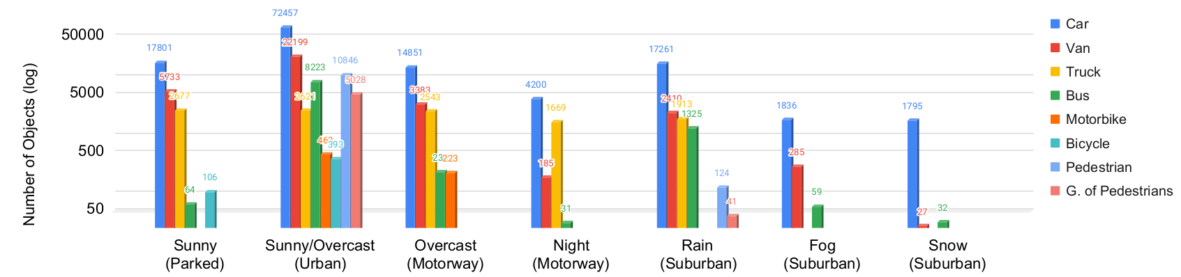
The dataset were collected in 7 different scenarios:
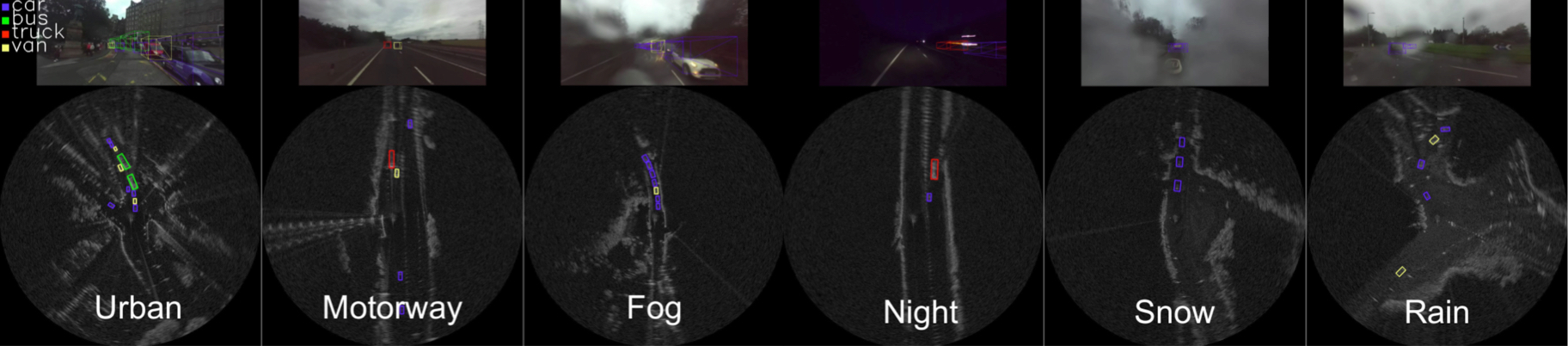
Sunny (Parked), Sunny/Overcast (Urban), Overcast (Motorway), Night (Motorway), Rain (Suburban), Fog (Suburban) and Snow (Suburban). 8 different types of objects, i.e., car, van, truck, bus, motorbike, bicycle, pedestrian and group of pedestrian, were annotated on the radar images. The figure below shows the numbers of individual instances labelled.
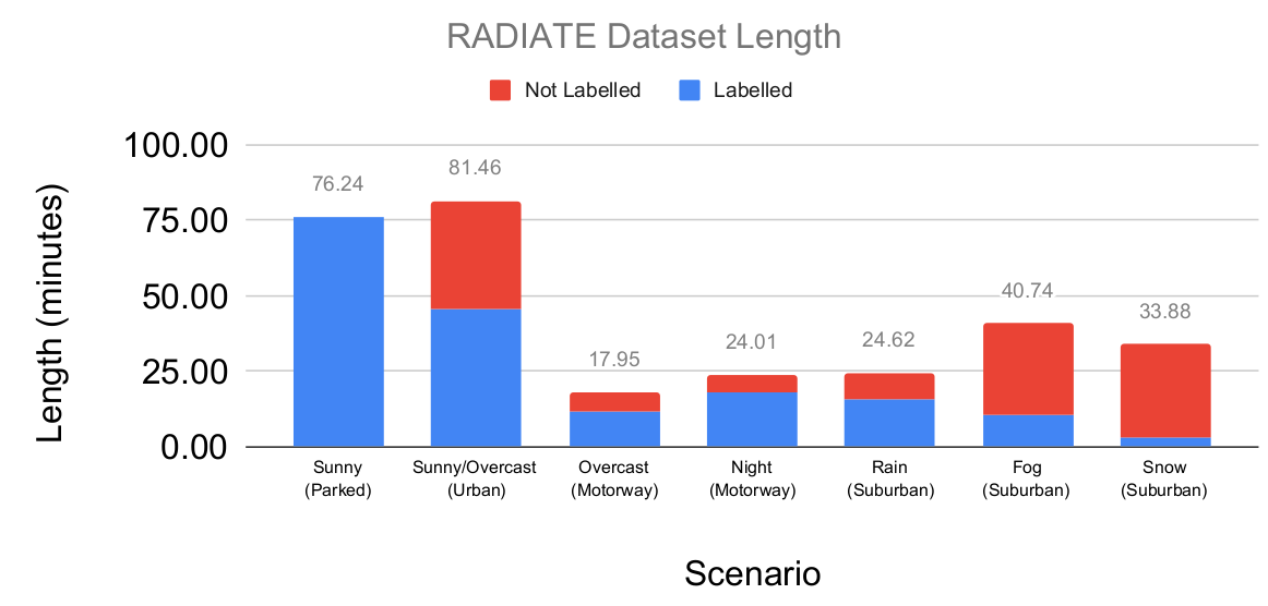
The sizes of the scenarios are as follows:
Sensors
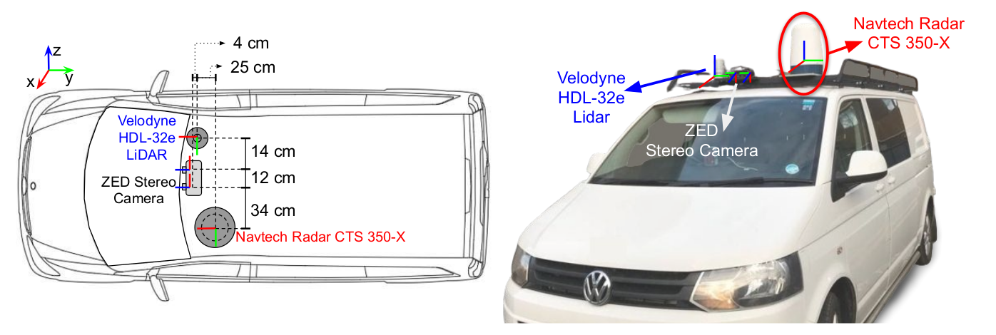
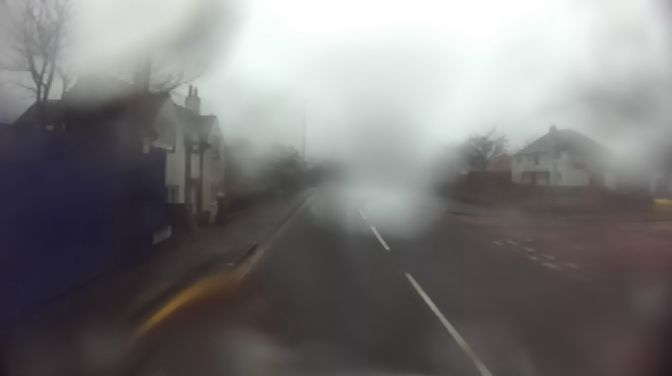
- Stereo Camera: An off-the-shelf ZED stereo camera was used. It was set at 672 × 376 image resolution at 15 frames per second for each camera. It was protected by a waterproof housing for extreme weather. Note the images in the dataset may be seriously blurred, hazy or fully blocked due to rain drops, dense fog and/or heavy snow.
- LiDAR: A 32-channel Velodyne HDL-32e LiDAR was set at 10Hz for 360° coverage. Since the LiDAR signal could be severely attenuated and reflected by intervening fog or snow, the point cloud data may be missing, noisy and incorrect for some sequences in extreme weathers.
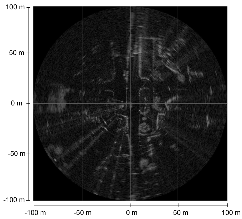
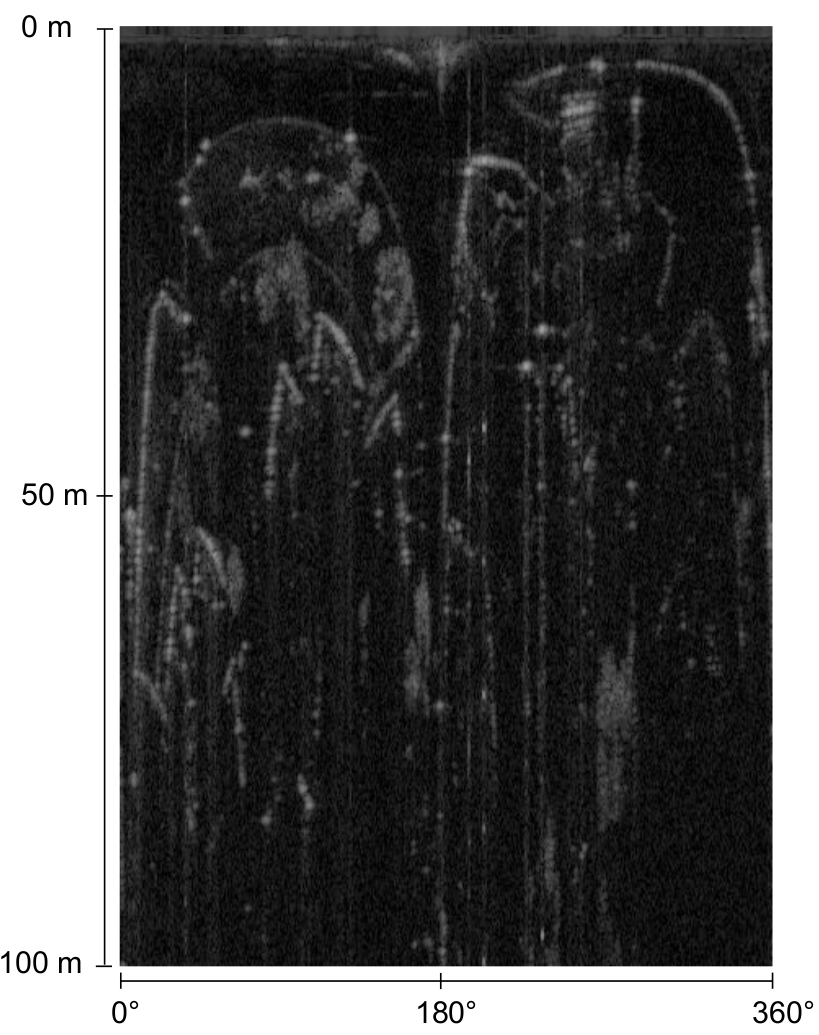
- Radar: RADIATE adopted the Navtech CTS350-X radar, a scanning radar which provides 360° high-resolution range-azimuth images at 4 Hz. It was set to have 100-meter maximum operating range with 0.175m range resolution, 1.8° azimuth resolution and 1.8° elevation resolution, Currently, it does not provide Doppler information.
- GPS/IMU: Advanced Navigation Spatial Dual GPS/IMU was equipped. It provides horizontal position accuracy 1.2 m, 0.5 m with SBAS and 0.008 m with RTK. Its full specifications can be found here.
Folder Structure and File Format
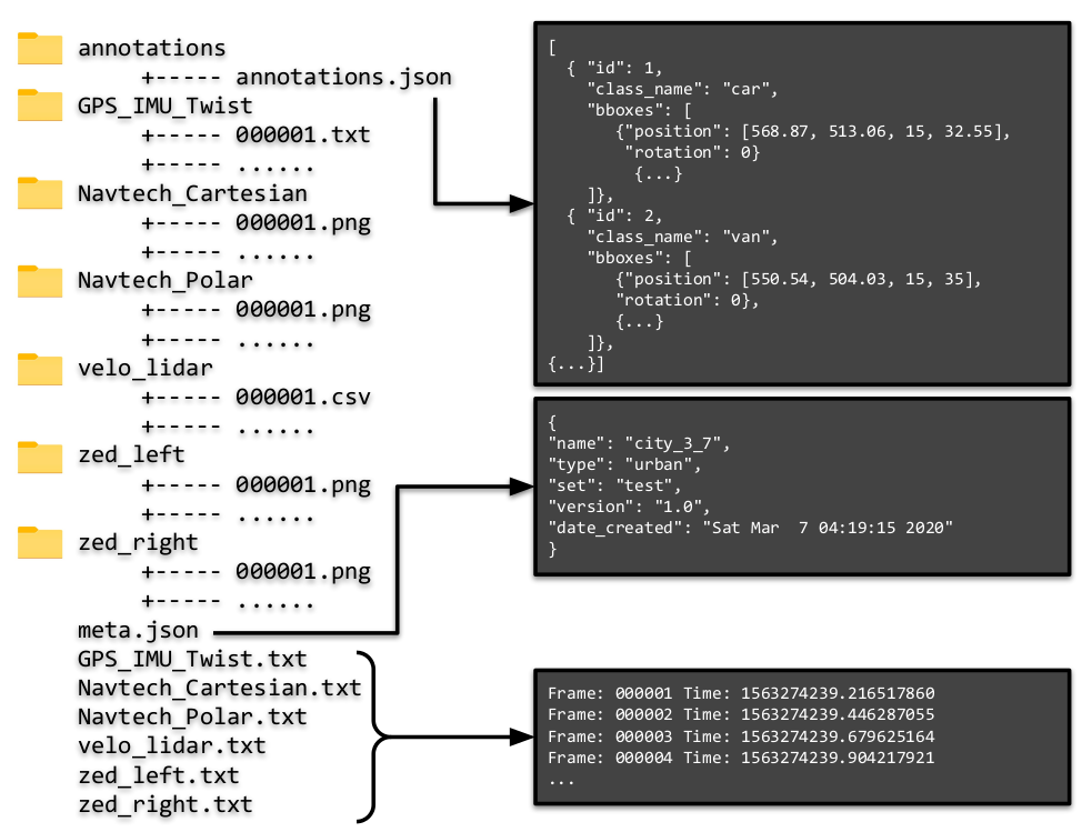
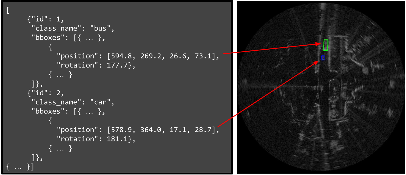
- annotations: The annotation is saved as a .json file, where each entry of a list contains
id,class_name,bboxes.idis the object identification.class_nameis a string with the class name.bboxescontainsposition:(x, y, width, height)where(x, y)is the upper-left pixel locations of the bounding box of the given width and height. Androtationis the angle in degrees using counter-clockwise.
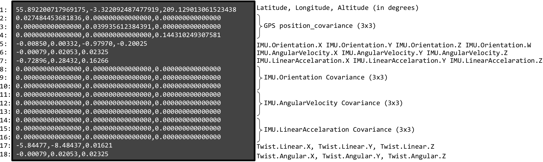
- GPS_IMU_Twist: A readable .txt file is provided for GPS and IMU. Each line is defined below:
    Line 1: Latitude, Longitude, Altitude (in degrees)
    Line 2-4: GPS position_covariance (3x3)
    Line 5: IMU.Orientation.X IMU.Orientation.Y IMU.Orientation.Z IMU.Orientation.W (Quaternion)
    Line 6: IMU.AngularVelocity.X IMU.AngularVelocity.Y IMU.AngularVelocity.Z
    Line 7: IMU.LinearAccelaration.X IMU.LinearAccelaration.Y IMU.LinearAccelaration.Z
    Line 8-10: IMU.Orientation Covariance (3x3)
    Line 11-13: IMU.AngularVelocity Covariance (3x3)
    Line 14-16: IMU.LinearAccelaration Covariance (3x3)
    Line 17: Twist.Linear.X, Twist.Linear.Y, Twist.Linear.Z
    Line 18: Twist.Angular.X, Twist.Angular.Y, Twist.Angular.Z
A GPS and IMU example file looks like:
- Navtech_Cartesian: Radar images in cartesian are provided as .png at 1152 x 1152 resolution. Nearest neighbour interpolation was used to convert the radar images from polar to cartesian. Each pixel in cartesian represents 0.17361m x 0.17361m.
- Navtech_Polar: Radar images in polar are provided as .png at 400 x 576 resolution, where each row represents the range
0m - 100mwith an resolution 0.17361m per pixel. Each column represents 1.1° in angle.
- velo_lidar: 3D Lidar point clouds are saved as readable .txt files, where each line represents a 3D point with
x, y, z, intensity, ring. (x,y,z) represents the 3D location of the point in lidar frame. Intensity [0-255] is reflectance captured by the sensor. Ring [0-31] means from which of the 32 channels the point was detected from.
    #x, y, z, intensity, ring
    -0.48352,-0.24456,0.01258,10,24
    -0.49561,-0.25068,0.0259,9,25
    -0.48782,-0.24673,0.038227,8,26
    -0.46912,-0.23728,0.049047,14,27
    -0.48393,-0.24477,0.063418,10,28
    -0.48104,-0.24331,-0.12773,0,13
-0.48602,-0.24582,0.076545,9,29-
zed_left/right: Unrectified stereo images were stored as .png files. They have 672 × 376 resolution at 15 Hz. The calibration parameters of the two cameras are provided. See Sensor Calibration for details.
Left Camera Right Camera 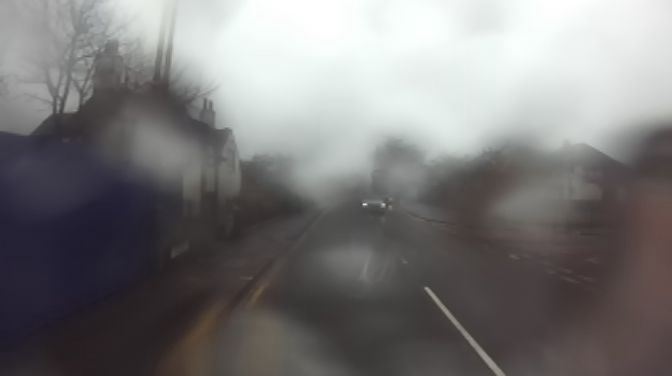
-
Timestamps: Each folder contains a set of sensor-named
.txtfiles which gives the timestamp of each collected sensor frame. Since the sensors operate at different frame rates, we simply adopted the arrival time of each sensor data as its timestamp. It is defined as:


Frame: XXXXXX Time: XXXXXXwhere Frame is the frame ID which corresponds to the filename. Time is the timestamp using UNIX time system in seconds.
    Frame: 000001 Time: 1574859771.744660272
    Frame: 000002 Time: 1574859771.977525228
    Frame: 000003 Time: 1574859772.213924306
Sensor Calibration
Sensor calibration is required for multi-sensor fusion and correspondence of sensors. The stereo camera were calibrated using the Matlab camera calibration toolbox and its intrinsic parameters and distortion coefficients are given. In terms of extrinsic calibration, the radar sensor is chosen as the origin of the local coordinate frame as it is the main sensor for RADIATE. The extrinsic parameters for the radar, camera and LiDAR are represented as 6 degree-of-freedom transformations (translation and rotation). They are performed by first explicitly measuring the distance between the sensors, and then fine-tuned by aligning measurements between each pair of sensors. The sensor calibration parameters are provided in the config/default-calib.yaml file in the RADIATE SDK.
The sensor calibration parameters calculated are as below.
#Radar calibration parameters
radar_calib:
    T: [0.0, 0.0, 0.0]
    R: [0.0, 0.0, 0.0]

#Lidar calibration parameters
lidar_calib:
    T: [0.6003, -0.120102, 0.250012]
    R: [0.0001655, 0.000213, 0.000934]


#Left camera calibration parameters
left_cam_calib:
    T: [0.34001, -0.06988923, 0.287893]
    R: [1.278946, -0.530201, 0.000132]
    fx: 3.379191448899105e+02
    fy: 3.386957068549526e+02
    cx: 3.417366010946575e+02
    cy: 2.007359735313929e+02
    k1: -0.183879883467351
    k2: 0.0308609205858947
    k3: 0
    p1: 0
    p2: 0
    res: [672, 376]


#Right camera calibration parameters
right_cam_calib:
    T: [0.4593822, -0.0600343, 0.287433309324]
    R: [0.8493049332, 0.37113944, 0.000076230]
    fx: 337.873451599077
    fy: 338.530902554779
    cx: 329.137695760749
    cy: 186.166590759716
    k1: -0.181771143569008
    k2: 0.0295682692890613
    k3: 0
    p1: 0
    p2: 0
    res: [672, 376]

#Stereo calibration parameters
stereo_calib:
    TX: -120.7469
    TY: 0.1726
    TZ: 1.1592
    CV: 0.0257154
    RX: -0.0206928
    RZ: -0.000595637
    R: [[0.999983541478846,   0.000655753417350, -0.005699715684273],
        [-0.000622470939159,   0.999982758359834,   0.005839136322126],
        [0.005703446445424, -0.005835492311203,   0.9999667083098977]]
SDK and Pre-Trained Models
We provide a Python Software Development Kit (SDK) for using RADIATE, and some pre-trained models for quick baselines on radar object detection, recognition, etc. Please click this page for more details.